

Hardware & wiring
Bill of materials
Section titled “Bill of materials”The vendor links are examples — any compatible part works. You also need wires, soldering equipment, a 3D printer for the case, screws and heat-shrink tubing.
| Count | Part |
|---|---|
| 1x | ESP32 (Lolin S2 Mini) |
| 2x | RS-485 transceiver board |
| 1x | W5500 Ethernet module |
| 1x | LED-button module |
| 1x | Male XLR socket |
| 1x | Female XLR socket |
Wiring
Section titled “Wiring”The circuit diagram below is the reference how we use the GPIOs. If you want to use different pins you can change the pin-definitions in src/boards/s2_mini.rs to match your setup.
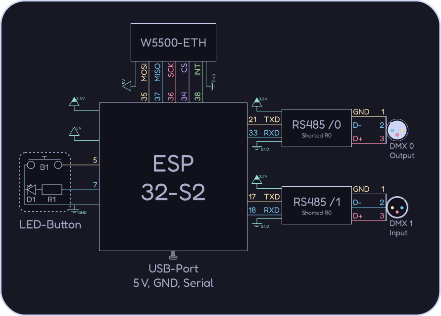
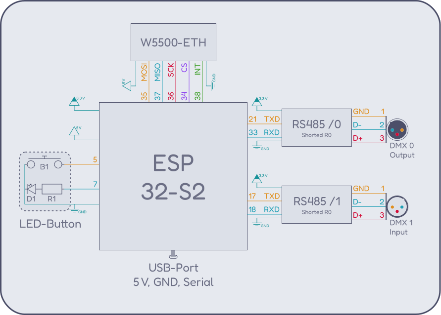
| GPIO | Usage |
|---|---|
| GND | Common ground |
| 3.3 V | VIN on RS-485 boards |
| 5 V / VBUS | VIN on W5500 |
| 0 | Onboard BOOT button |
| 5 | External button |
| 7 | External status LED (via MOSFET) |
| 15 | Onboard LED |
| 16 | RS-485 DE/RE direction |
| 17 | DMX UART1 TX |
| 18 | DMX UART1 RX |
| 21 | DMX UART0 TX |
| 33 | DMX UART0 RX |
| 34 | W5500 SPI CS |
| 35 | W5500 SPI MOSI |
| 36 | W5500 SPI SCK |
| 37 | W5500 SPI MISO |